
Blog
Why 3D Models Can’t Be Directly Laser Cut?
Laser cutting is an efficient 2D sheet process, yet many customers submit 3D models (STEP/IGES) expecting “direct cutting.” In practice this causes missing holes, incorrect dimensions, material waste and assembly issues. This article explains why and provides practical design and engineering unfolding (flat-pattern) tips to reduce rework and cost.
Why a 3D model cannot be used directly for laser cutting?
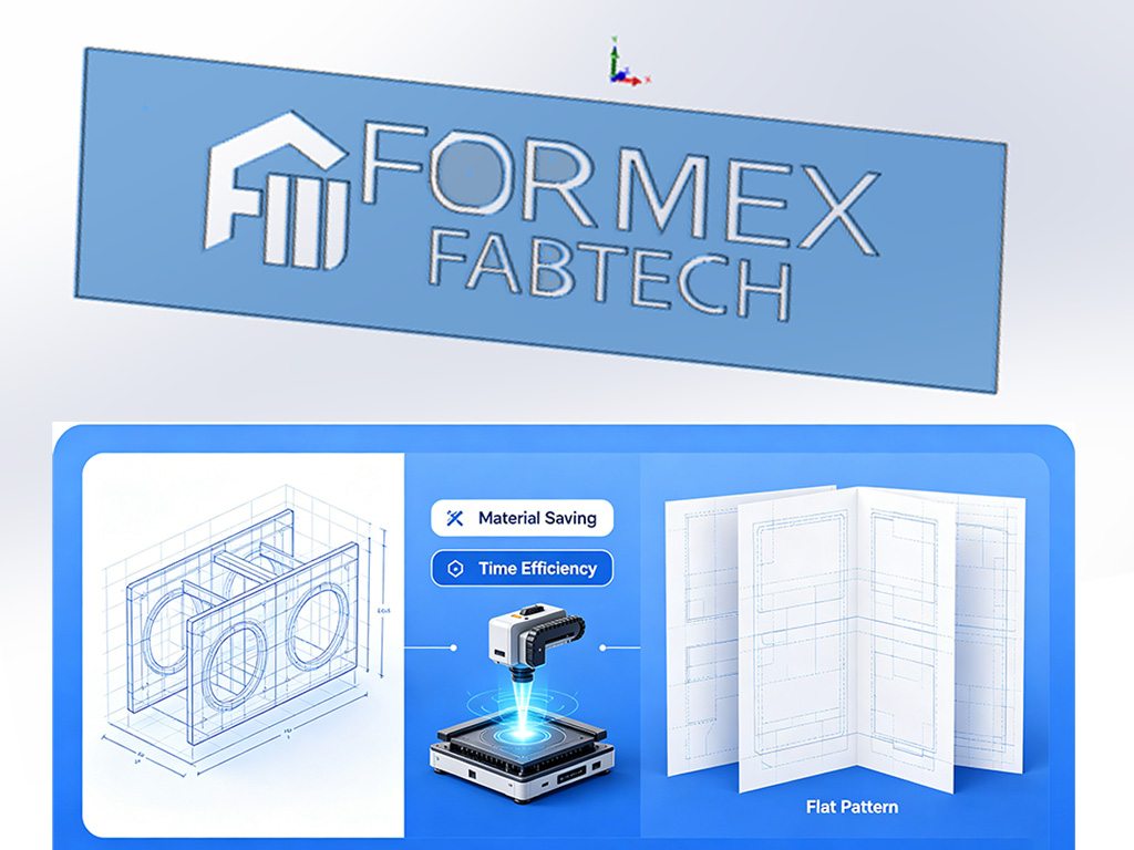
- Laser cutting is a 2D process: machines cut flat outlines. A 3D model contains bends, thickness and 3D features but not a flat unfolded contour (flat pattern).
- Missing flat pattern data: 3D files usually lack bend compensation, K-factor and the changes to hole positions caused by bending, so cut parts won’t match formed 3D dimensions.
- Non planar features: 3D local forms (stretches, chamfers, curved transitions) alter boundaries or hole geometry when flattened and must be handled by an engineer.
- Kerf and manufacturing tolerance ignored: 3D models often don’t account for kerf width or process tolerances that affect fit and assembly.
🌟Common problems and root causes (practical examples)
- Exported flat files missing holes or with wrong hole positions:
Holes created by 3D operations (boolean cuts, feature hierarchies) can be lost or turned into part boundaries when exporting.
- Hole/slot/arc size changes after bending:
bend allowance and deformation change distances; without compensation, dimensions shift.
- Splitting parts to save material:
Splitting increases nesting efficiency but requires careful joint design and post assembly operations (weld, rivet, fasten).
- Complex 3D/curved surfaces can’t be cut directly:
Non-developable surfaces must be approximated by segmented panels or redesigned for manufacturability.
🌟Practical design tips for laser cutting (avoid rework)
- Provide a flat pattern (DXF/DWG) at 1:1 whenever possible. If you supply a 3D model, include an unfolded flat pattern or ask engineering to produce one.
- Hole and spacing rules: minimum hole diameter ≈ 1–2 mm (thin sheet) or >= material thickness; hole-to-edge and hole-to-hole spacing ≥ material thickness unless otherwise specified.
- Minimum feature width & inner corners: avoid slots/narrow features narrower than material thickness; use fillets for internal corners with radius ≥ 0.5×thickness.
- Kerf compensation: account for kerf (typically 0.1–0.5 mm) in CAD or CAM for critical fits.
- Bend compensation (K-factor / bend allowance): specify material thickness, inside radius and K-factor so the folded part matches the 3D intent.
- Joint design for split parts: define seams, overlap widths, weld/tack locations, alignment holes or tabs for assembly.
- Marking & deburring: indicate marking/printing areas to avoid interference with welding or bending; specify deburring requirements.
🌟Engineer unfolding (flat-pattern) checklist
- Determine if surfaces are developable or need segmentation; choose split lines that minimize distortion.
- Calculate and apply correct bend allowance/K-factor and export the flattened DXF.
- Design mating/assembly features (tabs, weld seams, alignment holes) and consider tolerance stack-up.
- Optimize part shapes for nesting—make contours regular and reduce isolated small parts.
- Recommend cutting order (e.g., cut holes before outer contours for stability) based on part geometry and fixturing.
🌟Manufacturing & cutting process notes (customer-facing)
- Cutting sequence: typically cut internal holes before outer profile; hold small parts with micro-tabs to prevent drop-out.
- Hole strategy: thin sheets can be laser-pierced; thicker plates may require punched or drilled holes for accuracy.
- Micro-tabs & breakout: use tabs to keep small pieces in the sheet during cutting; remove and finish after.
- Thermal distortion control: long, narrow or thin parts warp more—use stiffening ribs, optimized toolpath, fixtures, or segmented cutting to reduce deformation.
- Nesting optimization: provide quantities and sheet size to get best nesting and lower unit cost.
🌟Cost-saving splitting (pros & cons) and engineering requirements
- Pros: better material yield, smaller sheet usage, lower cutting time/cost.
- Cons: adds assembly operations (welding/rivets/fasteners), potential loss of strength or cosmetic issues, cumulative tolerance risk.
- Engineering job: design joints, specify assembly tolerances, allow weld/finish allowance, and validate fit with prototypes.
🌟File & delivery requirements (what customers should upload)
- Preferred: 1:1 flat DXF/DWG with bend lines, or STEP + unfolded view with explicit bend compensation.
- Include: material grade, thickness, tolerances, surface finish, quantity, sheet size and critical dimensions.
- Layer convention: separate layers for cut profile, pierced holes, bend lines, and markings to streamline CAM import.
🌟Quality control & acceptance recommendations
- First article check: produce one flat and one formed part to measure hole positions and critical dimensions before mass production.
- Functional validation: perform assembly fit checks and strength/functional tests as required.
- Surface & post finish coordination: specify when painting/plating is to occur relative to cutting/bending and cleaning.
Quick pre-order checklist for yours
Laser cutting is straightforward only when 3D intent is translated into proper 2D flat patterns and manufacturing rules.
Early involvement by a sheet metal engineer to produce unfolded DXFs, apply bend allowances and design joints will eliminate rework, reduce material cost and shorten lead time.
We can evaluate your 3D files and deliver machine ready DXFs plus cost optimization suggestions—send your files to get a manufacturability review.